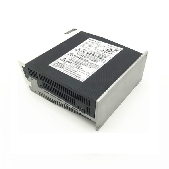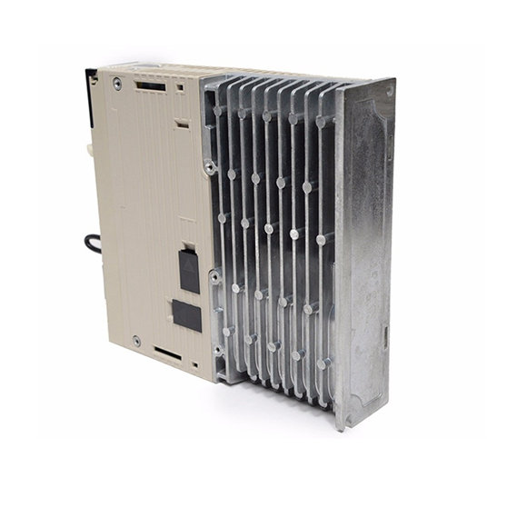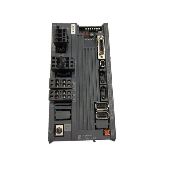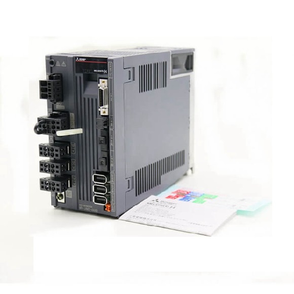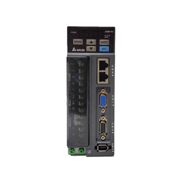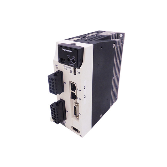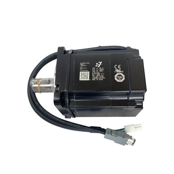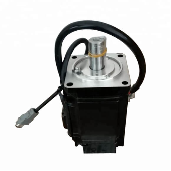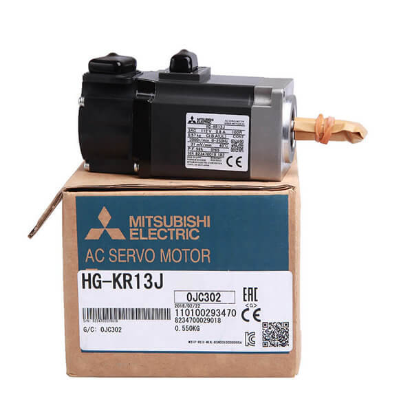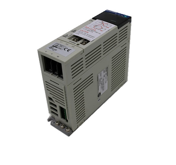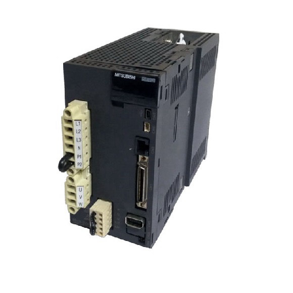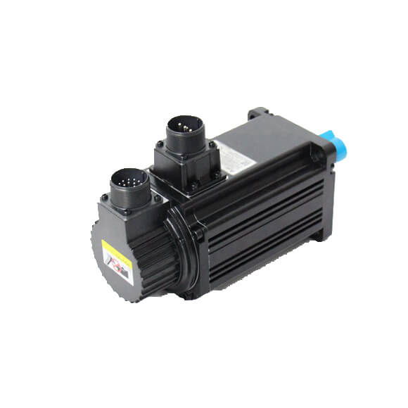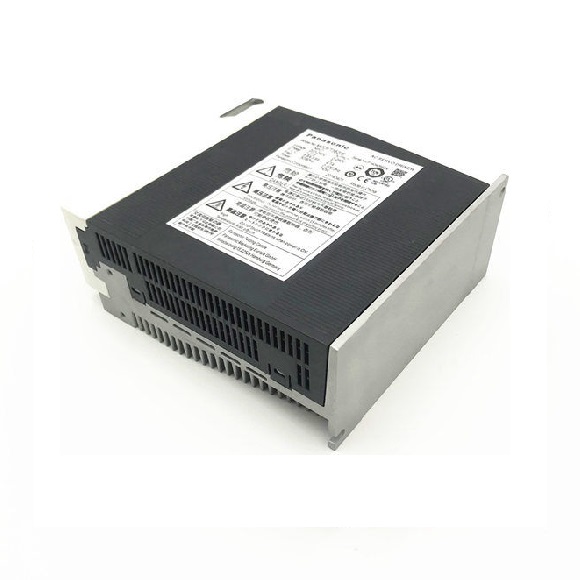
Panasonic Servo Drive MINAS A5 E series 750W MCDHT3520E/E02/CA1/MCDKT3520E/CA1
$1.00
Part Number
Series#: MINASA5
Model
Series#: MINASA5
Brand
Others
Material
Others
▌Product Description
Product Details
Series#: Panasonic Servo Drive Product Details Panasonic Servo Drive MINAS A5 750W MCDHT3520E/E02/CA1/MCDKT3520E/CA1 We are First Class Panasonic servomotors dealer and Panasonic servomotors distributor in China. We can Supply Panasonic electric automation parts,such as Panasonic PLC,Panasonic Servo Motor&Panasonic servo drive,Panasonic VFD,Panasonic Relay and Panasonic Sensor. 100% Original and new,In stock by Panasonic Electric Delivery time: Ready in stock and 1 days for ship out MOQ: 1pcs
Specification
| Basic Specifications | Input power | Single phase, 100 V | Single phase, 100 V to 115 V +10 % 50 Hz/60 Hz | ||
| –15 % | |||||
| Single phase, 200 V | Single phase, 200 V to 240 V +10 % 50 Hz/60 Hz | ||||
| –15 % | |||||
| 3-phase, 200 V | 3-phase, 200 V to 240 V +10 % 50 Hz/60 Hz | ||||
| –15 % | |||||
| Environment | Operating : 0 ˚C to 55 ˚C, Storage : –20 ˚C to 65 ˚C (Max.temperature guarantee 80 ˚C for 72 hours <Nomal temperature>) | ||||
| Temperature | |||||
| Humidity | Both operating and storage : 90 %RH or less (free from condensation) | ||||
| Altitude | 1000 m or lower | ||||
| Vibration | 5.88 m/s2 or less, 10 Hz to 60 Hz (No continuous use at resonance frequency) | ||||
| Withstand voltage | Should be 1500 VAC (Sensed current: 20 mA) for 1 minute between Primary and Ground. | ||||
| Control method | IGBT PWM Sinusoidal wave drive | ||||
| Encoder feedback | 2500 P/r (10000 resolution) incremental encoder | ||||
| Control signal | Input | 7 inputs (1) Servo-ON, (2) Alarm clear and other inputs vary depending on the control mode. | |||
| 4 outputs (1) Servo alarm, (2) Alarm, | |||||
| Output | (3) Release signal of external brake and other outputs vary depending on the control mode. | ||||
| Pulse signal | Input | 2 inputs Supports both line driver I/F and open collector I/F. | |||
| 4 outputs Feed out the encoder pulse (A, B and Z-phase) in line driver. | |||||
| Output | Z-phase pulse is also feed out in open collector. | ||||
| Communication function | RS232 | 1 : 1 communication to a host with RS232 interface is enabled. | |||
| Display LED | (1) Status LED (STATUS), (2) Alarm code LED (ALM-CODE) | ||||
| Regeneration | No built-in regenerative resistor (external resistor only) | ||||
| Dynamic brake | Built-in | ||||
| 3 modes of (1) High-speed position control, (2) Internal velocity control and | |||||
| Control mode | (3) High-functionality positioning control are selectable with parameter. | ||||
| Functions | Position control | (1) CW over-travel inhibition, (2) CCW over-travel inhibition, (3) Deviation counter clear, | |||
| Control input | (4) Gain switching, (5) Electronic gear switching | ||||
| Control output | (1) Positioning complete (In-position) | ||||
| Pulse input | Max. command pulse frequency | ||||
| Line driver : 500 kpps, Open collector : 200 kpps | |||||
| Differential input. Selectable with parameter, ((1) CW/CCW, (2) A and B-phase, (3) Command and Direction) | |||||
| Type of input pulse train | |||||
| Electronic gear | |||||
| (Division/Multiplication) | Setup of electronic gear ratio Setup range of (1-10000) × 2(0-17)/(1-10000) | ||||
| of command pulse | |||||
| Smoothing filter | Primary delay filter or FIR type filter is selectable to the command input. | ||||
| Internal speed control | (1) CW over-travel inhibition, (2) CCW over-travel inhibition, (3) Selection 1 of internal command speed, | ||||
| Control input | (4) Selection 2 of internal command speed, (5) Speed zero clamp | ||||
| Control output | (1) Speed arrival (at-speed) | ||||
| Internal speed command | Internal 4-speed is selectable with control input. | ||||
| Individual setup of acceleration and deceleration are enabled, with 0 s to 10 s/1000 r/min. Sigmoid acceleration/deceleration is also enabled. | |||||
| Soft-start/down function | |||||
| Zero-speed clamp | 0-clamp of internal speed command with speed zero clamp input is enabled. | ||||
| Common | Auto-gain tuning | Estimates the load inertia in real-time in actual operation and sets up the gain automatically corresponding to the machine stiffness. Useable at (1) High-response position control, (2) Internal speed control and (3) High-functionality position control. | |||
| Real-time | |||||
| Estimates the load inertia with an action command inside of the driver, and sets up the gain automatically corresponding to setup of the machine stiffness. Useable at (1) High-response position control, (2) Internal speed control and (3) High-functionality position control. | |||||
| Normal mode | |||||
| Masking of unnecessary input | Masking of the following input signal is enabled. | ||||
| (1) Over-travel inhibition, (2) Speed zero clamp, (3) Torque limit switching | |||||
| Division of encoder feedback pulse | 1 P/r to 2500 P/r (encoder pulses count is the max.). | ||||
| Protective function | Hardware error | Over-voltage, under-voltage, over-speed over-load, over-heat, over-current and encoder error etc. | |||
| Software error | Excess position deviation, command pulse division error, EEPROM error etc. | ||||
| Traceability of alarm data | Traceable up to past 14 alarms including the present one. | ||||
| Damping control function | Manual setup with parameter | ||||
| Setup | Manual | Console | |||
| Setup support software | PANATERM (Supporting OS : Windows98, Windows ME, Windows2000, and WindowsXP) | ||||